
G’day! If adelaide house painters you’ve ever thought about giving your home a fresh coat of paint, you’ve probably wondered what a professional house painter actually does. Is it worth …
Sewing Machine Parts and Their Uses

Sewing machine parts may seem complex at first glance, but each component’s function can be easily understood through this article. Here you will gain an understanding of their purposes and …
The Pros and Cons of Circumcision for Men
Sydney circumcision clinic has been a medical procedure since the time of ancient Egypt and other civilizations. Although most commonly associated with boys, circumcision has also been performed on females …
How to get Conveyancing allowance for School Buses
Conveyancing is a costly expense, especially if your goal is to obtain financing for a large property or to purchase it. If managed properly, this cost can be used as …
Various Types of Painting Services

There are two types – oil paints, and acrylic paints in Painters Brisbane. The first is easier to work with, but it also costs less. Commercial painters will do …
Learn how to draw landscapes
adelaide landscapers drawing can be difficult. This skill requires patience and hard work for beginners. A landscape design that is well-done can enhance the beauty of any home or office. …
Security Guards Employment – What’s the Big Deal?
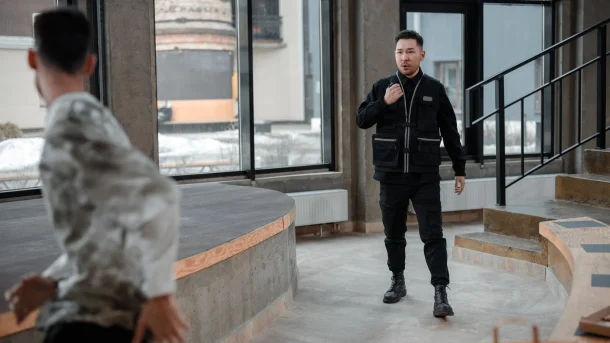
Security Security guards Melbourne guards are needed all over the world. It’s easy to find work as well as a job with a security guard company. In most states, you’ll …
Benefits of a Concrete Slab Foundation
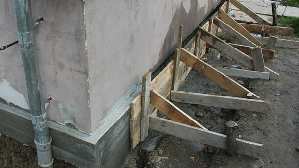
A slab foundation is a flat piece of concrete on which your home sits, eliminating the need for floor joists and significantly cutting utility costs.
To build a slab, footings …
What Kind of Will Lawyers Are Available?

There are many types of will lawyers on the market. It can be difficult to choose which one is right for you. This article will help you make the right …
Martial Arts at Home

Martial arts are possible at home. You can learn many different martial arts from the comfort of your home if you have internet access. Here’s a list of the best …
